Sunday, August 11, 2013

Quick filament drive update

It's been a bit hot in my garage to spend any significant time in there, but I did get most of the XY Stage prototype running. There is supposed to be a second plate on the right hand side, but it's stiff enough without it, so I'll wait until it's a bit cooler to machine it.


There is a small geometry error in the carriage design, I set the spacing for the bolts used to secure the fishing line from the outside edge of the bolts instead of the center. This actually results in measurable error, about 0.4mm as the carriage moves from extent to extent across the bar in the H. So I need to print a new carriage.
The XY Stage is attached to the Arm based electronics, and I need to make a couple of changes to the firmware before I can do any real speed testing, since it doesn't really support acceleration. For point of reference in the video the motion is at about 140mm/s with instantaneous change in velocity (i.e. that's the jerk and velocity setting). I also need to add support for the modified kinematics.
In the mean time if I get a chance I'll set up a test to see if there is any measurable error accumulation over a few hours.

Thursday, June 20, 2013

E3D V4 Hotend - follow up

In the end I couldn't reliably print PLA with the original E3D V4 Hotend, Sanjay from E3D was nice enough to send me a complete replacement, plus some extras.
I spent 3 or 4 days printing PLA with the new hotend, and while I can get good results from it, I don't think it's an ideal solution for printing PLA.

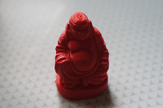
First I want to sow you how good a print the hot end can produce, this print is in Ultimachine Natural ABS 0.2mm layer height, the model is scaled by 50 %.
I doesn't photograph particularly well, but looks really good, it's hard to find something to criticize about the print. Perhaps the best way to describe prints from the E3D Hotend is "sharp", it does a great job of with detail, as good or better than any Hotend I've used.

The following is the small army of buddhas that are my attempts to get a really good PLA print out of the Hotend.

This army does not include the many complete failures I had early on, any attempt with too aggressive a retraction setting (anything over 2mm on my boden setup) resulted in a print failure with the Hotend jamming. Any attempt to print under ~225C resulted in a jam and failure.
The really observant of you will have noticed that although most of the prints are actually very good they all have issues when printing the head. The forwards most print is perhaps the best of them, so lets take a closer look.


It's somewhat hard to see, but if you look closely what happened in the print, is that at the start of a layer the flow of plastic did not immediately resume. Very shortly afterwards when it did resume, the pressure that had built up during the "stall" caused excess plastic to be extruded part way into the layer, producing the distinct ring on the forehead.
What you can't see without watching the print is why this happens, there are two very distinct places when printing the model where the cooling settings cause the print head to greatly slow down, one is at the top of the coat and one at the point you can see the issue. Some of the models have similar issues at the first point.
What I believe happens is that the retracted filament sticks to the inside of the stainless thermal break when it's primed, and the low extrusion rate isn't enough to overcome this additional force. The pressure slowly builds during the layer and when extrusion resumes you get all the excess plastic deposited very quickly.
My reason for believing this is that you can see it happen when the hotend is blocked, it simply will not extrude, the stepper will stall trying to drive more filament in, you wait perhaps 30s or retract 30mm of filament, and suddenly you see a lot of very liquid filament spew out and the Jam is cleared.
You appear to be able to reduce this effect by increasing the temperature of the print, but I don't have enough cooling to print PLA at much more than 235C (where this print was done) without it introducing other issues.

Now this particular model is particularly challenging at this scale, and I have printed several other PLA pieces that look very good, but there are plenty of none all metal Hotends that will also print this model without the issue.

My conclusion is if you don't print a lot of PLA then this Hotend is really very good, and well worth the investment, the fact that E3D have been responsive in dealing with problems is a big plus as well.
If you primarily print PLA I'd wouldn't by any all metal Hotend right now with the intent of using it as your primary Hotend.
I'm beginning to think that there is no perfect single hotend and the right approach is to have at least 2 and make it fast and painless to swap between them, which I suppose gets back to my 3D printer automatic tool changer idea...
Sunday, June 2, 2013

A better filament drive?


Ever since I saw Sublime's Tantillus 3D printer using spectra fishing line, I've ben really intrigued by the idea, in fact I built 2 Hbot prototypes using the idea.
The fundamental issue that comes up is that the fishing line "walks" as it wraps around the pulley, this changes the angle of the line, which in turn affects the tension. The problem is worse on a HBot because of the single long belt the number of times that the belt wraps around the pulley to go extent to extent can be large. In fact on my first prototype where I didn't try and address this there is a noticeable change in tension.
There are basically two way to approach the drive Tantillus passes the line through the "pulley" and wraps the filament on and off, this makes it impossible for the line to slip, but it's also difficult to address the walking filament, on Tantillus the combination of short axis and linear line path make this a minor issue that doesn't seem to impact the print quality.
The other option is to have sufficient friction on the drive pulley to prevent slipping, this requires a significant contact area between the line and the pulley and significant tension on the line.
The idea of the figure 8 line drive above is to use an idler to continually reset the filament position, basically the drive pulley in this case has 4 grooves, and the idler 3 that are offset by 1/2 the groove spacing. The filament always rolls onto the top groove on the drive pulley and off the bottom one.
There is no filament walking, and the equivalent of multiple wraps around the drive pulley to provide additional friction.
You can see the prototype running here


As a point of reference I'm running it off the LPC1768 based electronics discussed in other posts.
The idler has 2 9mm bearings in it's center.
I stole the idea for this from somewhere, I think the first time I ever saw it suggested was on the CNC Zone forums regarding wire drives for routers.
I'm pretty happy with the friction from the 3 figure8's, I might reduce the groove spacing on the drive and idler from 1.5mm to 1mm, but 1.5mm seems to work well.
My intent is to use this mechanism on my 4th HBot prototype, though I intend to use the CoreXY mechanics rather than the HBot mechanics, I have most of the X/Y Gantry laid out in CAD, hopefully I can get the CAD work complete this week.


Sunday, May 26, 2013

Ultimaker style XY gantry


I've been on and off experimenting with HBot designs, there are some videos of a couple of my prototypes on YouTube here and here if your interested. The issue that arises is that the belt geometry introduces a racking force that if the design is not extremely rigid causes crosstalk in the motion as the carriage moves across the bar in the H.

The Ultimaker design has many of the same advantages, notably static motors resulting in low moving mass,  the above video was a simple X/Y stage I put together so I could better understand the pros and cons.

The obvious con with the Ultimaker design is that the outside travel rods also rotate, so you can'y use LM8UU style bearings there. I'm using 1 inch long bronze bushings on 5/16 drill rod. Again I can't use 8mm rods because an 8mm precision rod won't fit in the 8mm hole of the 608 bearings I'm using to support the rod. The rods for the cross piece are 8mm and on them I'm using LM8UUL bearings since they do not rotate.

There is surprisingly little play in the design, the coupled belts remove almost all of slop.
The design is however extremely sensitive to alignment, towards the end of the video above you can hear one of the bushings vibrating, that's caused by the cross piece being very slightly askew resulting in increased static friction on the bushing. I fixed it just after shooting the video by loosening two of the pulleys and adjusting the alignment.

I have a couple of other issues in this prototype, the printed corner pieces aren't really rigid enough and it needs something to stop the 7/16th's rod moving in the 608 bearings, but it's pretty promising.

I have some parts here for 4th HBot prototype, my intent is to use the CoreXY mechanics this time, it looks like it resolves the issue with unwanted racking forces. So it should make an interesting comparison. I just need to make some time and finish the design.


Saturday, May 4, 2013

ARM motion controller Part 2

Ok so we don't want to solve a quadratic equation every time we make a step.

We want all of the moving axis to be move in a synchronized way, and be able to implement acceleration on top of that with a minimal additional cost.

The idea here is to decouple the acceleration from the linear motion, if we pick a fixed step rate and quantize all of the axis motion to that rate, then we could just treat the motion itself as linear and then change that rate independently to implement acceleration.

The nice thing about this is that acceleration calculation  is completely decoupled from the step interrupt, this is nice because the acceleration calculation still involves a divide which isn't cheap on the microcontroller.


The requirement of all the axis being synchronized is now also easy, the problem become analogous to a simple line drawing algorithm, it just happens to be in N dimensions which as we'll see later doesn't actually make it any more complicated.


So what should we select as our initial "fixed step rate"?

It must be high enough so that you are not required to do more than one step on any given axis per interrupt.
We could pick some arbitrarily high number, but this would result in interrupts where no steps are emitted and that would limit our maximum speed. And starve the rest of the system of CPU resources.
Instead it's better to pick the longest axis in our multidimensional line, compute a step rate based on than and it's initial velocity, such that it would output exactly one step per interrupt.
We then just need to determine if for any given step on that axis we need to output a step on the other axis as well.

There are a couple of ways to approach this, we could implement a DDA with fixed or floating point math, though this would accumulate error over the length of the line because of the limited number of bits in the representation, or we could just use the Bresenham line algorithm which uses only integer math, and therefore introduces no error in addition to the necessary quantization.

I'll quickly derive the bits of the Bresenham algorithm we need here, but Wikipedia has a pretty nice description if you're interested, though it only discusses two dimensions extending it to n is trivial.

The basic DDA is something like this for a stepper driver

// Primary axis is trivially the longest one 
select a primary axis P

// Initialize
foreach axis A
    Ad = (Aend -Astart)/(Pend-Pstart)
    Apos = Astart+0.5;   //Center of the "pixel"

// Steps
foreach step in P
    foreach axis A
        Aposnew = Apos + Ad
        if (Aposnew != Apos)
            output step for this axis
        Apos = Aposnew

It's a relatively easy to realize you don't actually need to track positions, just the fractional portions of them and you end up with.


// Primary axis is trivially the longest one 
select a primary axis P

// Initialize
foreach axis A
    Ad = abs((Aend -Astart)/(Pend-Pstart))
    Aerror = 0.5;

// Steps
foreach step in P
    foreach axis A
        Aerror += Ad
        if (Aerror >= 1)
            output step for this axis
            Aerror -= 1;

Looking at the above algoritm the only error we introduce is computing Ad where we have to divide by (Pend-Pstart), so all Bresenham does is multiply everything through by that and you end up with.


// Primary axis is trivially the longest one 
select a primary axis P

// Initialize
Plength = abs(Pend-Pstart)
foreach axis A
    Ad = abs(Aend -Astart)
    Aerror = Plength >> 1;

// Steps
foreach step in P
    foreach axis A
        Aerror += Ad
        if (Aerror >= Plength)
            output step for this axis
            Aerror -= Plength

Now we can do everything with integers, no multiplies, our only divide is a divide by two which can be done as a trivial shift (the bottom bit doesn't really matter). All dropping the bottom bit in the divide by two above does is offset the concept of the pixel center very slightly. It would in fact be entirely "correct" to pick any pixel center, but picking 0.5. 0.5 results im more natural looking lines. If its something that you think is significant you can multiply everything through by two.


What's our accuracy with the new approach?
Since we're quantizing steps in the none primary axis to steps on the primary axis, we are accurate to ~1/2 a step.
In practice I think this ends up being more accurate that the original implementations, because of rounding error introduced in the original when converting velocities to frequencies.


Sunday, April 21, 2013

E3D V4 Hotend

I did some printing with Nylon a few months ago, I was running my hotend at ~245C for a lot of it which is getting close to the point where both the PEEK and the PTFE liner would be damaged. In fact when I stripped the hotend down to change the nozzle I did see signs of damage to the PTFE liner.

Several all metal hotends using a stainless steel thermal break have started to appear on the market, and I ordered the E3D one when they went up for sale.
This is what's in the package.


It's pretty much everything you need to build it, including the alan keys for the set screw and the bolts to mount the fan. E3D has assembly instructions on it's website, they are straight forwards and following the yields something like this.


The purple part is a mount designed for a JHead from http://www.thingiverse.com/thing:60539
Since I was replacing the hotend anyway I took the opportunity to add some inline connectors to make removing it easier.
Here it is mounted on the Rostock Max


Some observations, without the fan the heatsink gets very hot, with it, it's cool to the touch even close to the thermal barrier.
I pushed some filament through by and it's somewhat interesting, there is some initial resistance, but one the filament is moving that seems to clear, more on this in a bit.
I plugged everything in, reset the Z Height on Max, I ended up losing about 12mm of Z, though that could be regained with bigger spacers.
I started a print using PLA and the hot end immediately jammed, after some messing about I did get the print started and it worked well until it jammed part way through the print.
After some experimentation I think the issue is that I ended up mounting the fan perhaps 10mm higher than the supplied fan mount and there is insufficient cooling at the base of the heat sink, this in turn is increasing the length of the melt zone and the PLA is doing what PLA does and jamming.

So I tried a different mounting configuration which allowed me to retain the original fan mount.


This seems to work better, but I still had a hell of a time getting the first layer down, it would get half way through and jam. In the end I set the temperature MUCH higher than I usually would for PLA, the print above is running at 250C. It doesn't behave like PLA at 250C, usually it has the consistency of water at that temperature.

So I pulled out my thermocouple and stuck it in the spare hole on the aluminum heater block, it reads 245C, so the thermistor isn't far off.  I've been printing the same plastic at 190C in the old hotend.
Best guess is the cooling fan is causing a significant thermal gradient in the AL block and as a result the temperature at the outside of the block is significantly different than the actual temperature of the brass nozzle. Unfortunately the thermocouple won't fit into the hotend itself, so I can't verify.

Anyway here's the finished print, really pretty good.


No conclusion at this point, I need to run more PLA through it and see if I can get a handle on how best  to make it work, and obviously run some ABS and Nylon through it.


Monday, April 15, 2013

Optical distance sensors

I've been looking for a good solution to automatic bed leveling, Nophead did some work on this a couple of years ago using a sensor that was deployed during a calibration phase. I've also seen a solution using a metal bed and the hotend itself as a probe.

The idea is simple enough measure 3 points to get the plain of the bed, adjust the incoming GCode to print parallel to it.

The same approach could be taken to auto calibrate a delta printer, though in this case you'd adjust the arm positions to all have the same step value at the same height. It's actually a little more complicated that this because the measurement point would be offset from the center of the head, but it's still relatively simple.

My original idea was similar to Nophead's, have a deployable probe and use a mechanical switch for the measurements, using a system where the head would be moved into a physical obstacle somewhere in the build envelope to deploy/retract the probe.

However a friend of mine pointed me at optical distance switches, used in robotics for obstacle detection.


After reading the datasheet, they are really pretty inaccurate, but in this application accuracy is irrelevant, all you need is 3 values relative to each other, so what matters is repeatability. Of course there is no information on that in the data sheet, so I ordered one from Pololu.

I spent most of the weekend writing a TCP stack for the LPC1768 board, but I did get a change to wire up the sensor and do some rough testing.
I attached it temporarily with some tape to me RostockMax's carriage, and jogged to turn the proximity LED on and off.


I wasn't expecting much, but it turns out it's remarkably repeatable. I would estimate in the 0.02mm range and certainly better than 0.05mm.
So now I have another project to get back to when I have some time...


Friday, April 12, 2013

ARM motion controller Pt1


I picked up a cheap LPC1768 dev board from EBAY, <$40 for a 100MHz ARM processor with a 2.8 inch 320x240 touch screen, with the intention of using it as a printer driver.

A couple of weekends ago I stuck a pololu 4988 stepper driver in a breadboard, ran a few wires, connected a stepper and plugged the step pin into one of the GPIO outputs. A couple of hours later I was running the motor off the board at speeds upwards of 1000RPM, all in all a promising test.

So the next task is writing a real motion controller, now I could just port one of the many existing reprap firmwares from arduino, or even have gone back to the original source and just ported GRBL, but where is the fun in that. For me half the reason for doing it is to better understand the what works and the limitations, and the core of a motion controller isn't actually all that complicated.

First thing I needed to do was be able to coordinate motors so that multiple axis would move together at a requested velocity.
My initial thought on implementing this was to use the RIT timer on the LPC which fires an interrupt when it reaches a comparator value.
Basically you compute the velocity for the move


And  from that compute the number of ticks for each axis


You then just figure out which axis moves next, and set the comparator to that value. at the end of that interrupt you repeat the process and update the comparator appropriately.
This has the advantage of only firing the interrupt when a step on an axis is needed, and the precision of the output is basically limited to a few timer clock pulse, given the clock is running at 25MHz that's pretty damn good precision.
So I built a simple event based system and wrote the code to set up movement across multiple axis. There were two issues.
The first was that as the Cortex-M3 which the LPC1768 is based on doesn't have hardware floating point, so I made the decision to do everything as fixed point, In attempting to retain as much precision as possible I ended up with a 64 by 64 bit divide (which is probably 200+ cycles) in the setup code. This on it's own I could have lived with and I could have probably done some things like breaking down long moves to remove it.
The second issue came up when I finally thought about implementing acceleration, every time a step is taken you have to determine when the next step should be, with constant velocity this is trivially just an add of the interval you calculated above, with acceleration you basically have to solve


for t for every step of every axis, accumulating error as you do so.
OK so we can make this work but is there a better approach?
Yes, but I'll leave it for the next entry.