Monday, April 15, 2013

Optical distance sensors

I've been looking for a good solution to automatic bed leveling, Nophead did some work on this a couple of years ago using a sensor that was deployed during a calibration phase. I've also seen a solution using a metal bed and the hotend itself as a probe.

The idea is simple enough measure 3 points to get the plain of the bed, adjust the incoming GCode to print parallel to it.

The same approach could be taken to auto calibrate a delta printer, though in this case you'd adjust the arm positions to all have the same step value at the same height. It's actually a little more complicated that this because the measurement point would be offset from the center of the head, but it's still relatively simple.

My original idea was similar to Nophead's, have a deployable probe and use a mechanical switch for the measurements, using a system where the head would be moved into a physical obstacle somewhere in the build envelope to deploy/retract the probe.

However a friend of mine pointed me at optical distance switches, used in robotics for obstacle detection.
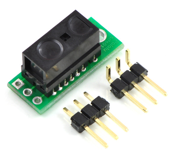

After reading the datasheet, they are really pretty inaccurate, but in this application accuracy is irrelevant, all you need is 3 values relative to each other, so what matters is repeatability. Of course there is no information on that in the data sheet, so I ordered one from Pololu.

I spent most of the weekend writing a TCP stack for the LPC1768 board, but I did get a change to wire up the sensor and do some rough testing.
I attached it temporarily with some tape to me RostockMax's carriage, and jogged to turn the proximity LED on and off.


I wasn't expecting much, but it turns out it's remarkably repeatable. I would estimate in the 0.02mm range and certainly better than 0.05mm.
So now I have another project to get back to when I have some time...


Friday, April 12, 2013

ARM motion controller Pt1


I picked up a cheap LPC1768 dev board from EBAY, <$40 for a 100MHz ARM processor with a 2.8 inch 320x240 touch screen, with the intention of using it as a printer driver.

A couple of weekends ago I stuck a pololu 4988 stepper driver in a breadboard, ran a few wires, connected a stepper and plugged the step pin into one of the GPIO outputs. A couple of hours later I was running the motor off the board at speeds upwards of 1000RPM, all in all a promising test.

So the next task is writing a real motion controller, now I could just port one of the many existing reprap firmwares from arduino, or even have gone back to the original source and just ported GRBL, but where is the fun in that. For me half the reason for doing it is to better understand the what works and the limitations, and the core of a motion controller isn't actually all that complicated.

First thing I needed to do was be able to coordinate motors so that multiple axis would move together at a requested velocity.
My initial thought on implementing this was to use the RIT timer on the LPC which fires an interrupt when it reaches a comparator value.
Basically you compute the velocity for the move


And  from that compute the number of ticks for each axis


You then just figure out which axis moves next, and set the comparator to that value. at the end of that interrupt you repeat the process and update the comparator appropriately.
This has the advantage of only firing the interrupt when a step on an axis is needed, and the precision of the output is basically limited to a few timer clock pulse, given the clock is running at 25MHz that's pretty damn good precision.
So I built a simple event based system and wrote the code to set up movement across multiple axis. There were two issues.
The first was that as the Cortex-M3 which the LPC1768 is based on doesn't have hardware floating point, so I made the decision to do everything as fixed point, In attempting to retain as much precision as possible I ended up with a 64 by 64 bit divide (which is probably 200+ cycles) in the setup code. This on it's own I could have lived with and I could have probably done some things like breaking down long moves to remove it.
The second issue came up when I finally thought about implementing acceleration, every time a step is taken you have to determine when the next step should be, with constant velocity this is trivially just an add of the interval you calculated above, with acceleration you basically have to solve


for t for every step of every axis, accumulating error as you do so.
OK so we can make this work but is there a better approach?
Yes, but I'll leave it for the next entry.